Project Page
Contents
The following project has been submitted by Pat M1BNH, a previous club member.
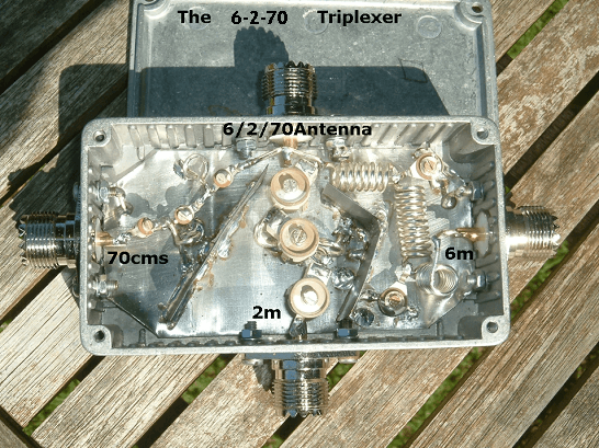
THE 6-2-70 TRIPLEXER
Based heavily on the HB9ABX Diplexer Article, plagiarised by Pat. Walton M1BNH
The TRIPLEXER below separates the following bands input to the top port:
- HF to 6m on the right-hand port (0 – 52MHz).
- 2m on the bottom port
- 70cm on the left port
It allows the simultaneous operation of 3 different equipments (HF, VHF & UHF) over one coax cable, or the use of 3 antennas for the corresponding bands with one coax cable.
The following data were measured at the 50Ω ports of the HB9ABX DIPLEXER:
– Attenuation of the other band is very high (over 60db)
– Insertion loss is negligible (less than 0.2db)
The circuit may be built easily into a solderable metallic box measuring about 11 x 5,5 x 3cm.
Here’s the circuit diagram of the Triplexer:
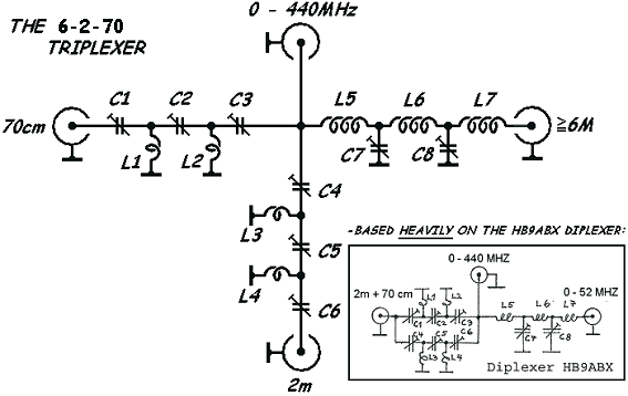
Component list: all coils made with 1mm diameter CuAg (Silvered Copper) wire
L1 = 1 turn 5mm id
L2 = same as L1, oriented 90° with respect to L1
L3 = 1 ½ turn 6 mm id
L4 = same as L3 , oriented 90° with respect to L3
L5 = 7 turn 6mm id, 15mm long
L6 = 11 turn 6mm id, 19mm long, oriented 90° with respect to L5
L7 = same as L5, oriented 90° with respect to L6
C1, C2 & C3 = foil trimmer cap. 9pf (0.5-9pf) see note in text
C4, C5 & C6 = foil trimmer cap. 32pf (3-32pf)
C7, C8 = foil trimmer cap. 135pf (5-135pf)
4 HF chassis plugs 50 Ohm (N-Type, BNC, SO239 to suit equipment)
1 metallic box with solderable inner (see below).
Coils may be made of silvered copper (CuAg) wire, but enamelled copper wire serves equally well. The layout should be symmetrical, otherwise undesired coupling may occur which hinders proper operation. Correct adjustment of the unit is very important. This requires some time and patience. Prior to each adjustment, make sure the SWR meter is calibrated exactly for all measuring frequencies and reads exactly 1.0 when terminated by dummy load and make sure that the dummy load is 50 Ohm on each band.
Adjustment procedure using a SWR meter:
1. Connect a 50Ω dummy load to the 0-440 MHZ socket on the triplexer. Fit suitable 50Ω terminations to all unused sockets.
2. Connect a SWR meter between the 0-52MHz socket on the triplexer and the 6m TRx and transmit a 51MHz carrier at low power. Adjust C7 and C8 to obtain 1:1 SWR. Then, with the SWR meter still set to ‘REVERSE’, turn the meter sensitivity to maximum and transmit and trim C7 and C8 again. NOTE C7 and C8 should reach the same value.
3. Connect a SWR meter between the 2m socket on the triplexer and the 2m TRx and Transmit a 145MHz carrier at low power. Adjust C4, C5, and C6 to obtain 1:1 SWR. Then, with the SWR meter still set to ‘REVERSE’, turn the meter sensitivity to maximum and transmit and trim C4, C5, and C6 again. NOTE C4 and C6 should reach the same value.
4. Connect a SWR meter between the 70cm socket on the triplexer and 70cm TRX and Transmit a 435MHz carrier at low power. Adjust C1, C2, and C3 to obtain 1:1 SWR. Then, with the SWR meter still set to ‘REVERSE’, turn the meter sensitivity to maximum and transmit and trim C1, C2, and C3 again. NOTE C1 and C3 should reach the same value.
5. Repeat steps 2 to 4 as necessary, as adjustment of one band influences the others. You will need some patience to reach proper adjustment on all bands.
Now the triplexer is ready for use. If an antenna analyser or VNA is available, use this instead of the SWR/ TX combination to make adjustment easier. Connect the analyser/VNA to plug 0 – 440 MHZ and dummy load to the plug being adjusted.
Note:
Foil capacitors can fail even at low power. Ceramic types (below) are stronger, good air trimmers are best.
As of 05/08/2020 this triplexer is now in use at M1BNH, connecting discrete UHF, VHF and 6m transceivers to a Diamond V-2000 antenna at a maximum RF power output of 25w.
Another project by Pat.
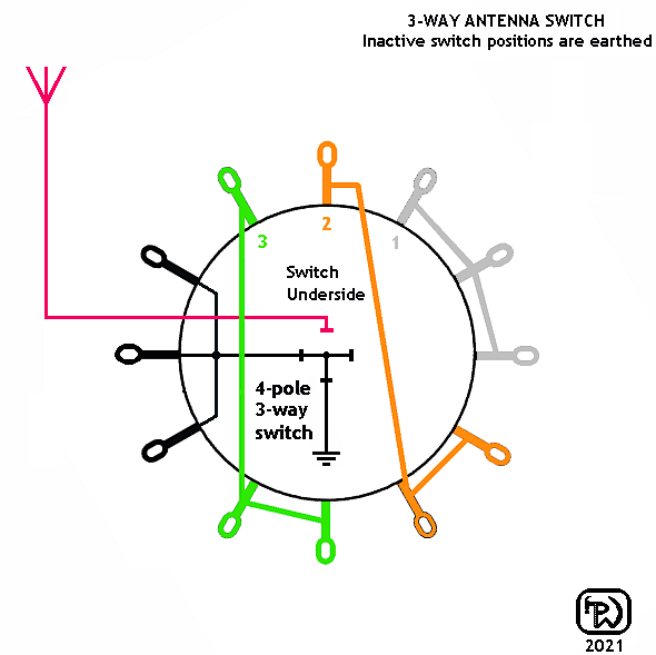
Three-Way Aerial Switch
I made a version of this switch nearly forty years ago (for CB) and still use it at HF today. I made another a few months ago and thought I’d write it up as a project for G3BRS.
Wiring Diagram
– Really only useful for low power (up to 25w or so) and excellent for switching between receivers.

Server Power Supply by Alan Drury G4FZP.
Server Power Supplies for Amateur Radio
With today’s modern rigs it’s often necessary to have a supply giving 13.8v at 20 amps or more. Purists would want this to be a traditional linear supply to avoid RFI, but these are big, heavy, can be inefficient and aren’t cheap or easy to build.
But by careful selection of the right unit it’s possible to repurpose a server power supply you can find on EBay for around 20 quid that is much smaller, lighter and won’t generate any RFI.
I claim no originality for or rights to this information, everything here has been developed and published by others and is freely available online (see Appendix for links). All I’ve done is collect the relevant bits of information together and collate them into one document that gives you all you need to know in just one place. And I’ve also performed these conversions myself and tested them so I know they work.
What to use
Not all supplies are easy to modify and some generate interference. Here are the two I recommend and have personally tried. Both are made by HP but can also sometimes be found branded as Compaq and a few other names.
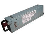
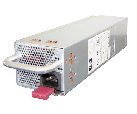
HP DPS-600PB

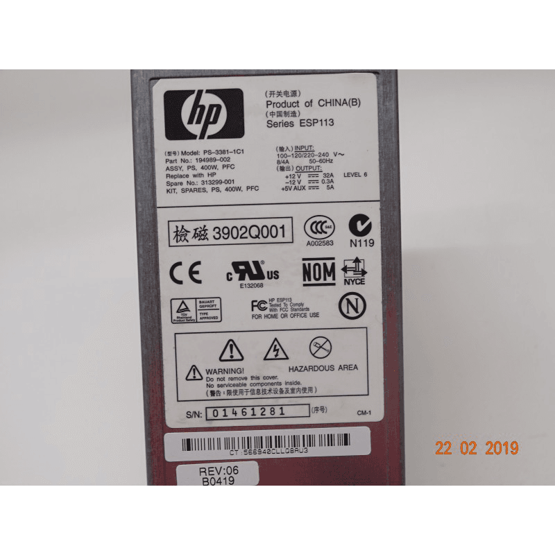
HP PS-3381
Safety
These server power supply modifications involve electrical understanding and skill. They are not hard to do, but you have to understand the basics, know what you doing, and have the skills to pull it off (including physical modification of the case and soldering small parts).
You will be working on mains powered equipment that is not isolated from the mains supply. If you doubt your ability to perform the work safely, get someone with more electrical experience to help you.
In short, you perform these modifications entirely at your own risk. Neither I nor Bury Radio Society accept any responsibility for any disasters along the way
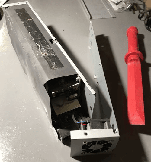
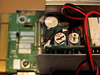
HP Server DPS 600PB Power Supply
These provide up to 47A at 12/13.8v. I use one to power my FT-991A and it handles everything the rig can throw at it with no detectable RFI when running at 100w input on the HF bands with the supply less than two feet away from the radio.
1. Opening Up
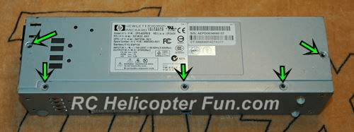
This is the easy part, only 10 screws to remove…
5 Screws On The Left Side
4 Screws On The Top
One Screw On The Right Side
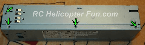
Many supplies come with an insulating wrap-around sheet inside the case that is glued in place. If you find you can’t get the case apart after removing the screws this is probably why. Loosen it it as necessary by prying down between it and the case until it comes free and you can move it of the way.
Once your DPS 600PB is opened up unplug the fan connector so that the top plate with the fan assembly can be set aside. There is usually some white mastic holding the plug in place – gently persuade it off with a knife or similar. You don’t have to remove the fan plug and top plate but it’s easier with it out of the way.
Fan Plug Location / Removal
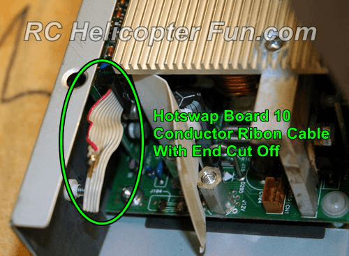
2. Remove Hot Swap Terminal
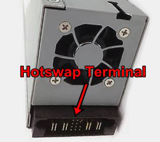
Most server supplies come with a “Hot-Swap” connector. This is just a dedicated plug that allows quick and easy field replacement of these units by a technician.
If you want to keep the hot-swap terminal on your DPS 600PB you can solder your output wires and jumpers direct to it. I recommend however you remove the hot swap connector and replace it with 4mm sockets/binding posts. These are ideal as they allow for both 4mm banana plugs and 1/4″ fork connectors for connecting your wires.
The hot swap connector sits on its own little mounting board. This is held in place by two screws and a nut, and there are two more screws that attach it to the positive and negative power posts inside the power supply. Remove all these screws and take out the hot-swap board but keep the screws – you’ll use them later on.
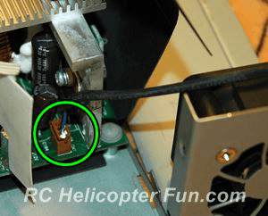
There is also a blue and a purple wire going from the main circuit board to the hot swap terminal circuit board along with a 10 conductor ribbon cable. Unclip the ribbon cable plug at the hot swap board end, and just cut the blue and purple wires close to the hot-swap board – leave a bit of length as we’ll be using one of them later on.
The photos to follow show these two wires and the ribbon cable in more detail.
3. Circuit Modifications
Modifications To The Wiring and Board
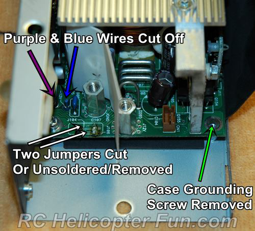
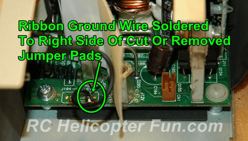
The photo above shows to cut off the blue and purple wires that went to the hot-swap terminal fairly flush to the circuit board. But as mentioned before, don’t do that – cut them at the hot-swap board instead and leave a length attached to the main circuit board. We’ll need them to adjust the voltage later on.
Floating the supply
This next part only applies if you want to ‘float’ the supply relative to the case because you intend to connect two or more DPS-600PBs in series for a higher output voltage. If you’re not planning to do this and you just want a single DPS-600PB producing 12 or 13.8v at 575w you can skip these steps.
The metal case will still be earth ground by way of the ground wire going to the mains – we are only floating the PCB (circuit board) negative output from the case, not the case itself from earth ground.
First, either desolder or just snip the two grounding jumpers on the main circuit board.
Next, remove the DC circuit board grounding screw and insulate the back side of the board to prevent it touching the mounting pillar underneath.
This can be accomplished with some electrical insulating card. A small piece cut from the bottom front of the supply where the hot swap board was works well. A small length of heat shrink folded a few layers thick underneath also works. Use some hot glue, epoxy, or silicone to hold the insulation in place.
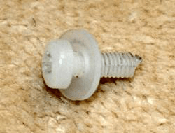
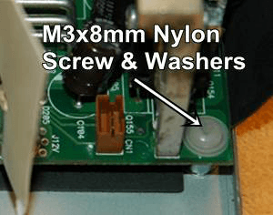
You don’t need a screw in there as it’s not absolutely necessary to have that corner of the circuit board mechanically attached. If you do want one, use a nylon M3x8mm insulating screw with an insulating washer on the front and back sides of the board.
After you finish insulating the board from the case and cutting/removing the two grounding jumpers; check for any continuity between the circuit board and the case with a multimeter. You could also check between the case and the negative output post/terminal. You want to see infinite resistance!
Getting the Supply to Start Up
Whether or not you opted to float the supply, continue from here.
Now we modify the ribbon cable. Cut the plug off the end and divide the cable in half (5 conductors in each half).
Divide and strip the first 5 wires (the outer most wire is red), twist, and solder them together. These 5 wires will be linked to DC ground. Doing this turns the power supply on and sets the fan speed to low while still allowing it to automatically speed up when needed.
If you want to include a switch or external control to turn the DC output on and off, put that switch in the ground wire described here. The mains part of the supply is always on when power is connected, this switch just turns the output on and off.
Finish by soldering the single ground wire from the ribbon to the right side of the jumpers on the main circuit board that you cut earlier, or direct to the circuit board if you desoldered them. Doesn’t matter if it’s the front or rear right jumper trace, both are electrically connected. If you didn’t cut them (because you don’t need to float the supply) just solder the wire onto one or both of the jumper wires. These jumpers are electrically connected to the negative power post located directly behind them so you could also connect to that if you find it easier. As long as it’s 0v or DC ground it’ll work.
Voltage Adjustment
The 8th wire in the ribbon cable is the voltage adjust. We need to wire that to the +5vSTBY output of the supply (this is the purple wire you didn’t cut off earlier) via a 1k trimpot. This will allow us to vary the voltage between 12v and 13.8v.
The easiest way to do this is to mount the trimpot on a small piece of board and fit that using a small screw and standoff inside the bottom of the case in the space where the hot-swap connector board used to be. A suitable hole drilled through the case will allow an INSULATED screwdriver to be inserted from outside to adjust the voltage once the supply is reassembled.
Note that the supply can become unstable and trip off at different loads depending on where you have the voltage set. Your mileage may vary, but without further modification with the output set to 13.5V mine trips at about 15A. At 13.4V, it is stable all the way up to 35A but trips at 40A. At 13.15V, it oddly trips at just 10A. At the default output of 12.5V it runs like a lion all the way up to and beyond 40A. If it does trip off while you’re testing you’ll need to disconnect the load and then unplug the incoming mains supply at the IEC connector and count slowly to 10 before reconnecting to allow everything to reset.
To fix the tripping issue permanently you need to modify the overvoltage protection circuitry (see later). But if you don’t want to do this and you find your supply doesn’t like your load and keeps shutting down, try changing the output voltage a little.
The remaining wires in the ribbon cable are not being used. Insulate them and make sure they can’t touch anything. For the curious, this is the pinout and what they do:
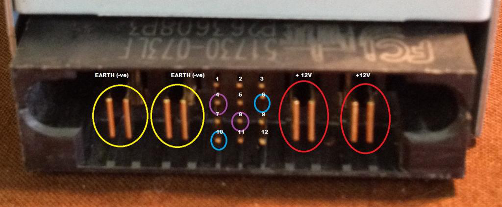
Hot-Swap Connector PIN Ribbon Cable Wire
1 +5VSB, not in ribbon, PURPLE wire
2 +5VSB, not in ribbon, PURPLE wire
3 +5VSB, not in ribbon, PURPLE wire
4 3 (FanSpeed)
5 -12V, not in ribbon – BLUE wire
6 5 (PsKill)
7 6 (not sure what this one does)
8 Ground, not in ribbon
9 8 (VoltageAdjust)
10 4 (PsOn)
11 9 (CurrentShare)
12 7 (not sure what this one does)
- The Red core in the ribbon cable is wire “1”, wire “2” is the one next to it and so on
- Shorting PsKill and PsOn to ground turns the supply on.
- Shorting FanSpeed to ground slows fan speed to minimum.
- Putting a 1K variable resistor between VoltageAdjust and +5VSB (the purple wire) allows voltage adjustment up to 13.8V.
- If multiple supplies are used together connecting all their CurrentShare pins together allows them to balance the load
Overvoltage Protection
This is very fast acting, so fast in fact that the transient voltage swings under varying load are what causes the supply to trip when being used above its normal output voltage.
You don’t have to perform this part of the mod (see the workarounds earlier), but if you want to, this is how you do it.
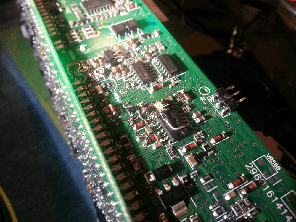
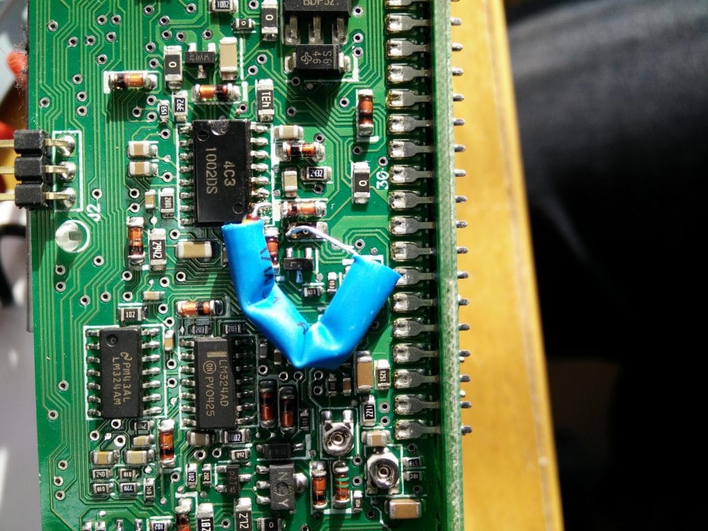
The protection IC, a 1002DS, isn’t publicly available. It is manufactured by Delta for use on their own power supplies (these supplies are made by Delta, just branded HP). Here is a partial schematic of a different Delta PSU using a DNA1002 chip. I assume 1002DS is pretty much the same chip as all the connections seem to match.
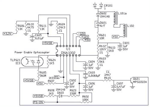
The chip senses the output voltage being fed to it on pin 10. Here is the chip in situ on the board, ringed in red with pin 10 arrowed:
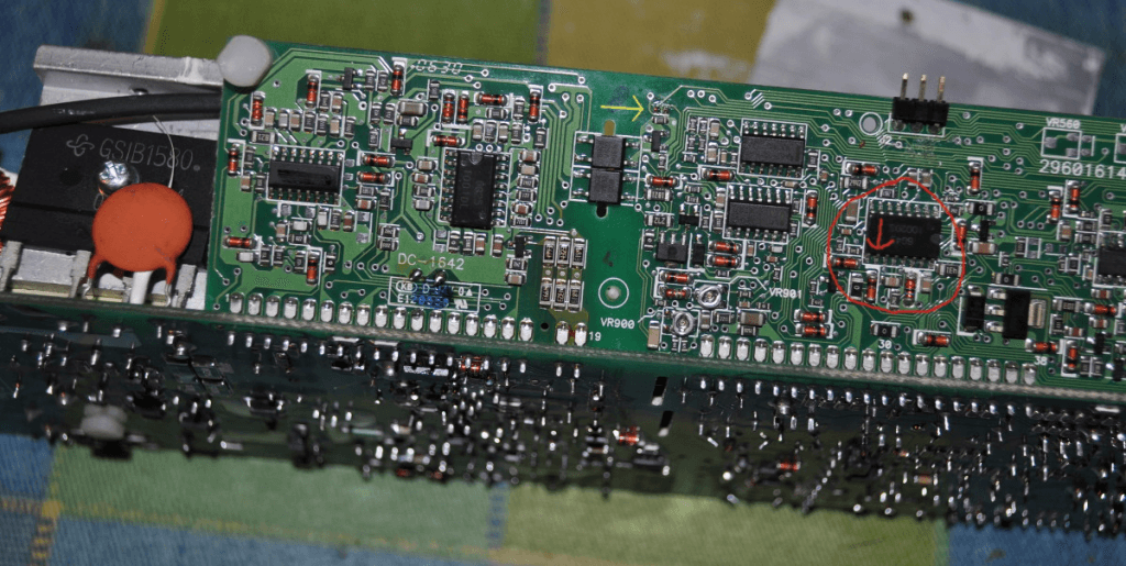
If you just cut pin 10, the chip sees 0V all the time on the 12V monitor pin and the overvoltage protection is completely disabled. You might not want to do that however if you have expensive gear attached.
A better approach would be to introduce a potential divider so the chip sees a lower input voltage than the one actually present at the output of the supply. In practice the potential divider doesn’t work too well, but you can do the same job with a LED. The average LED drops around 2V when conducting, so the incoming ’12V’ voltage is effectively lowered by 2V and fed to pin 10 on the 1002, allowing the output to rise 2V beyond the level at which the OVP usually kicks in.
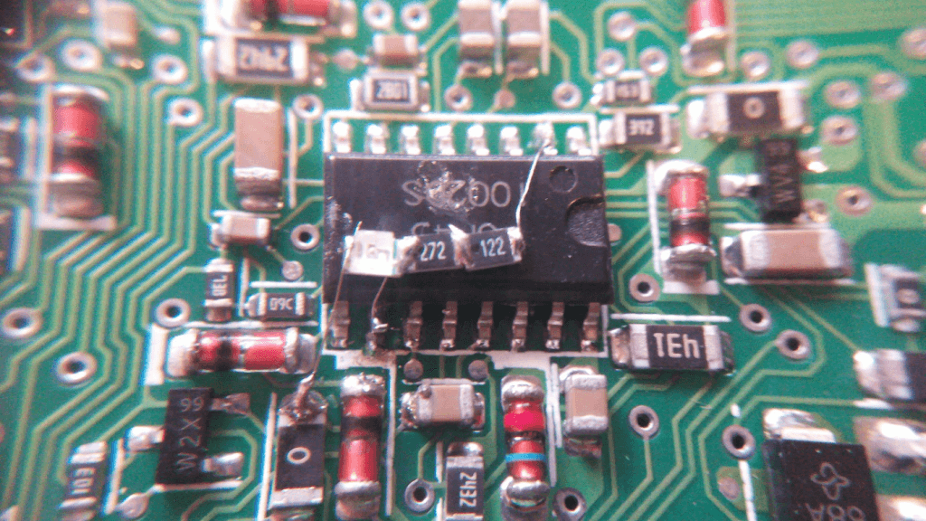
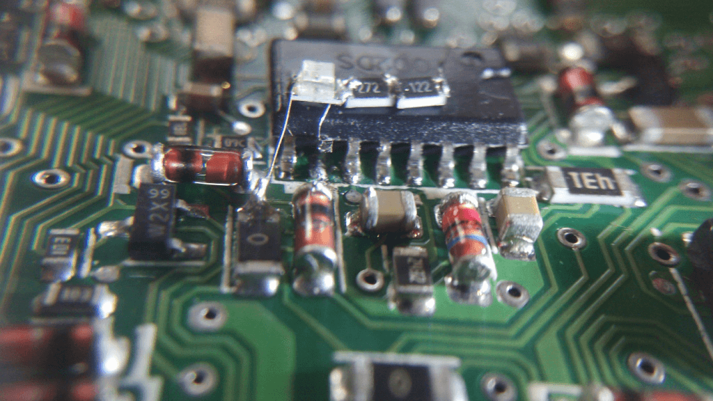
To actually construct this you have to unsolder and lift pin 10 into the air. This isn’t easy. But once you’ve managed it you can then either use surface-mount parts directly on top of the chip as shown in the photos, with short leads connecting down to the various pads, or you can simply attach thin wires to the connection points and use standard components elsewhere, perhaps on a bit of board, taped up or tucked out of the way inside a piece of heat-shrink tubing.
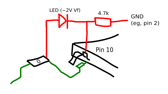
When measured the little LED used here dropped 1,7v rather than 2v, so the 4.7k was replaced with 2.7k and 1.2k in series:
If you don’t want to go down the LED route you could also use a few ordinary diodes in series to achieve the same end result:
Whatever you do, keep your work compact and close to the board as the case of the supply has to go back on properly afterwards.
4. Dual Terminal Block Connection & Installation
Now we need to sort out the output connections. To do that you need to rig up something like this:
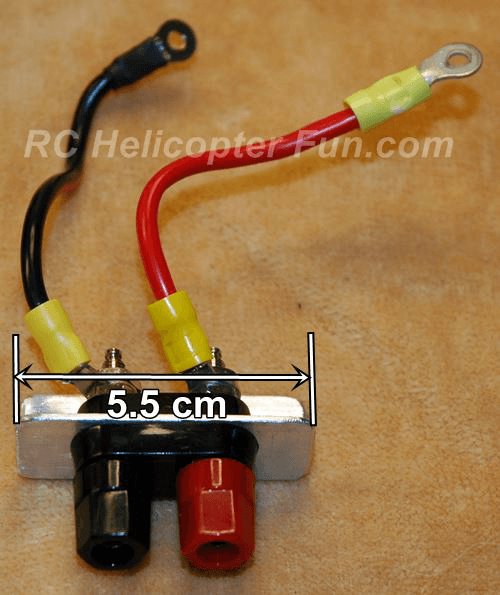
4mm Dual Terminal Block Mounted To 3/4″ 1/16″ Thick Aluminium Angle
Make the angle plate a suitable size to fit neatly on the back of the finished power supply. Use thick good quality cable for the connections from the terminals and finish the leads with suitable terminals to screw on to the output posts inside the supply. You saved the screws for the terminal posts earlier so you can use them again.
The two threaded bushes in the case that previously held the hot-swap board will be ideally placed to secure your angle plate. Just drill a couple of holes and use the screws you saved from earlier.
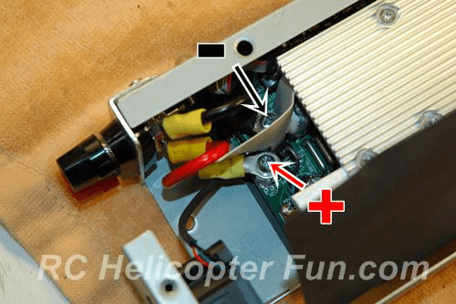
Positive & Negative Post Positions
Make sure all the screws and the nuts for the connectors are nice and tight; you’ll be drawing a fair amount of current through them.
Plug the 3 pin fan connector back in (assuming you removed it earlier), and refit the top plate and fan assembly. You may have to angle the terminal on the positive post downward slightly to allow adequate fan clearance.
5. Reassemble
First have a really good look inside to make sure all wires are nicely positioned, you haven’t left any screws or bits behind and nothing will get pinched or shorted when the covers are replaced.
Replace the plastic insulating sheet in its original position and then the covers, making sure all the screws are back in place.
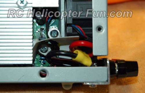
Shown above is the output terminal angle bracket mounted using the threaded inserts that are already in the bottom of the power supply.
Also shown are some little self-adhesive rubber feet that provide a finishing touch and help stop the unit sliding around.
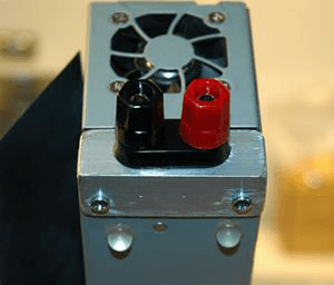
HP PS-3381 Power Supply
I’ve managed to get one of these power supplies powered up and working ok.
It’s rated at 32A and I’ve had it running at 20A without it getting warm at all. Again, no RFI when powering the FT-991A.
It’s not as neat a finished result as with the DPS-600PB as you can’t remove the hot-swap connector. With these, the connector is actually a protruding piece of the circuit board which you’re pretty much stuck with. But, that said, you can end up with a working supply even quicker and easier than with the DPS-600PB if you don’t mind how it looks.
Here’s the solution:
- Simply connect the 3 pins in the photo to ground. There are four grounds/negatives, these are the ends of both sides of the board.
- The +12v output is the long middle section on the top
- Connect all 4 grounds together and this is your negative
To make a low voltage switch just put a switch inline between 11,15,23 and ground. If that doesn’t work just switch pin 15.
As for 5v, should you need it, I’m sure its the fat track just right of 23.
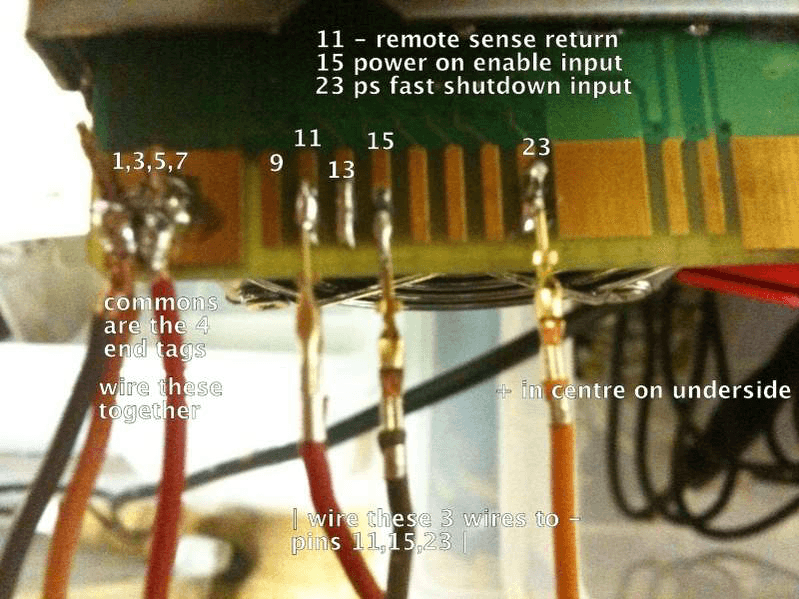
Here’s the connector information:
PIN# FUNCTION DESCRIPTION
1-8,37-44 RTN Power and Signal Return
9 SPARE Spare position (No connection)
10, 12, 14, 16, 18,20,22 +12V +12V Output
24,26,28,30,32,34,36
11 RS RTN Remote Sense Return
13 +12VRS +12V Remote Sense
15 PSON# Power-On Enable Input
17 HB Hard Boot Input
19 12LS 12V Load Share Bus
21 DCOK +12V Output OK Signal
23 PS KILL Power Supply Fast Shutdown Input
25,27 29 5VSB +5V Standby Output
31 -12V -12V Output
33 FANV Power Supply Fan Voltage Input
35 PRESENT# Power Supply Present Signal
You could try connecting the Remote Sense (pin 13) to the +12V output. May make it more stable. I’ve never found a problem with without pin 13 and didn’t see any difference when I connected it.
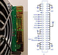
Voltage and Protection Adjustments
To get at these you’ll actually have to remove the case!
Inside you’ll see these two pots:
The right pot controls the output voltage. With the control pins connected to ground as suggested, turning the pot counter-clockwise increases the output voltage to 13.2-13.25V. The unit trips off at just over 13.25V, it works ok at 13V.
The left pot controls the OverCurrent Protection. Turning it far left allowed me to push the supply very hard. I took 42A at 12.8V for 2 minutes – that’s almost 540W! Turning the pot to the right makes the unit shut down earlier.
For future use, mark out carefully where these pots are and drill two access holes in the case. You can then adjust these from the outside once the unit is reassembled using an INSULATED screwdriver.
The Fan
You’ve probably realised by now that the fan sounds like some sort of demon-possessed hover mower about to take off.
Bad news – you can’t use pin 33, the fan power supply voltage pin, to easily control the speed, and the internal fan HAS to be connected for it to start!
But the fix is easy. Just put a 4.7v zener diode in series with the fan lead and now the fan will be almost silent but still moving air.
If you decide to replace the fan with a quieter lower power one the supply might not start. Wire a 220ohm 1w resistor in parallel with the lower-powered fan to get around this.
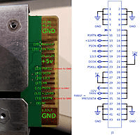
Getting up to 13.8v
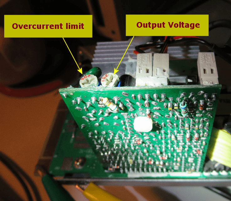
This involves two steps. First is to increase the voltage adjustable range to about 14.0V using a 68K resistor so that the user can trim the output voltage to 13.8V.
However, the internal over voltage protection will then be triggered so we have to take care of that in the second step. An additional 6K8 resistor will increase the trip point to 14.45V.
The attached image shows before and after the modification. You can use regular 0.25W axial resistors too.
The track/component layout on your board may look slightly different to the ones shown above but you should be able to figure it out. Mine was slightly different where the 68K resistor goes.
Just remember to keep your wiring flat and close to the board so that the power supply cover will go back on okay, and make sure you insulate everything.
Appendix – List of Online Sources
https://www.rcgroups.com/forums/showthread.php?1369612-My-take-on-the-HP-server-power-supply
http://vk2rh.com/computer-power-supply/
https://www.rchelicopterfun.com/dps-600pb-build.html
Audible RF Sniffer
Here’s a simple piece of test gear that you can knock up in an evening and yet is surprisingly useful to have around.
The original design is by VK3YE and he calls it “The squeakie”. He has lots of projects on his website and his YouTube channel is also worth a look.
Here’s the circuit:
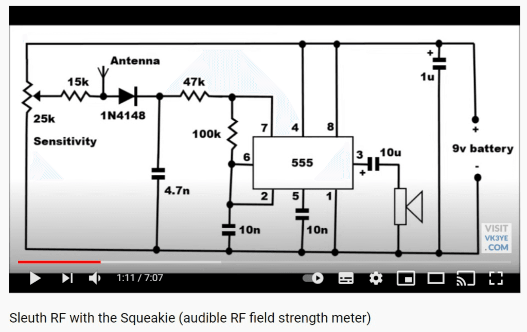
The 555 timer is configured as a voltage-controlled-oscillator. The control voltage is set by the 25k pot which sits across the supply rails and which is set to the point at which the 555 just stops oscillating. Any RF picked up by the antenna gets rectified by the diode and added on top of this bias voltage which pushes the 555 back into oscillation. The more RF there is, the higher the control voltage gets pushed and the higher the pitch coming from the speaker.
The only thing I added to the circuit above was an on-off switch. I used a miniature toggle switch in series with the battery but if you have a suitable pot with a built-in switch that would do too.


The unit is simple to build and very tolerant in terms of layout etc. A piece of veroboard works just fine and so does ‘dead bug’ construction. A linear pot will give the easiest operation and the speaker can be any small 8 ohm type. A small plastic project box makes a good enclosure and you can mount a telescopic aerial on the top for ease of use. Just mount the pot, speaker, aerial and on-off switch on the box, put the battery and circuit board inside and you’re good to go.
To use, switch on, extend the aerial and with no RF around turn the pot until you hear a note. Now turn the pot back slowly, making the pitch of the note lower and lower until you reach the point where the pitch gets so low that the note stops. This is the point of maximum sensitivity. Now, generate some RF nearby and you’ll hear the note rise, the more RF you’re detecting the higher the pitch will go.
The circuit is unsurprisingly more sensitive at lower frequencies but even at UHF is still quite usable. Mine can detect a Baofeng UV-5R on 144.550 MHz from nearly three metres away and my Allstar node from about a metre.
What can you use it for? Well, detecting and tracking down RF sources obviously, but also confirming your transmitter is working, looking for RF leakage, tuning equipment or aerials for maximum output (the hands-free audible indication is a godsend here) or even as a CW sidetone for a QRP transmitter that doesn’t have one built in. Not bad for something you can knock up in an evening for about the price of a pint.